This step-by-step guide covers the cable assembly, electrical integration and testing for an Oculus Sonar on a BlueROV2 vehicle.
Components Required
· Oculus Sonar
· Oculus 2m Cable Whip
· BlueROV2
· BlueROV tether and Fathom X interface module
· BlueROV2 ethernet switch (sold by Blue Robotics)
· RJ45 to JST GH Adapter (included with ethernet switch)
· BlueROV2 WetLink Penetrator (sold by Blue Robotics)
· Assembly tools: screwdriver, allen key and spanner set
· Soldering equipment
· Heat shrink tubing (2.4mm diameter)
· Heat gun
· Cable measuring, cutting, and stripping tools
Cable Assembly
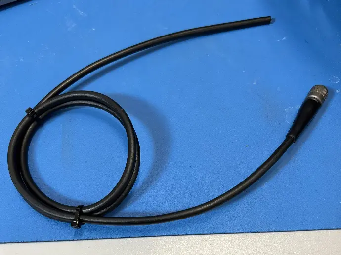
Step One
Take the Oculus 2m cable whip.
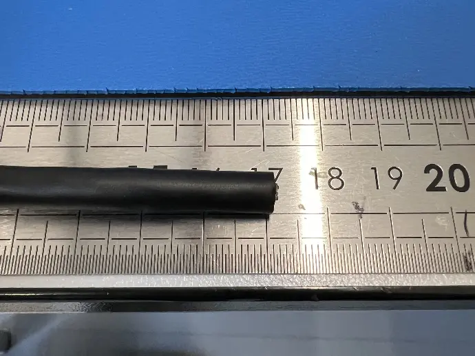
Step Two
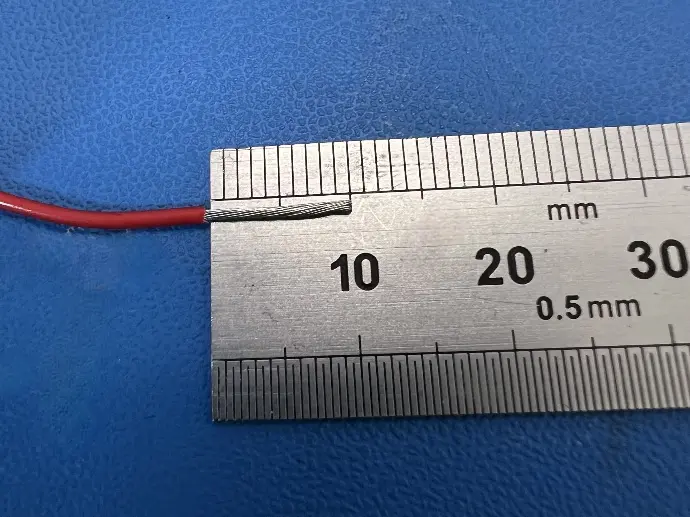
Measure out 170mm.
Step Three
Using a sharp scalpel,
cut at the 170mm mark and remove the outer coating.
Take care not to damage the wires
inside.
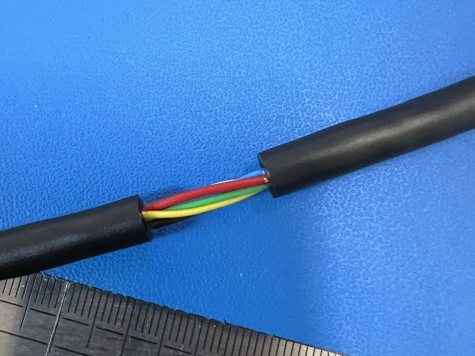
Step Four
Pull the outer coating off the wires. It may be necessary to cut it
down into smaller pieces for easier
removal.
Step Five
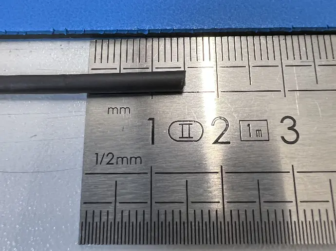
Cut 4 x 15mm lengths of heat shrink
tubing (2.4mm diameter).
Step Six
Strip back around 3mm from the
four data wires (blue, white, green,
and yellow.) Slide a piece of heat shrink over
each wire.
Step Seven
Take the JST connection loom.
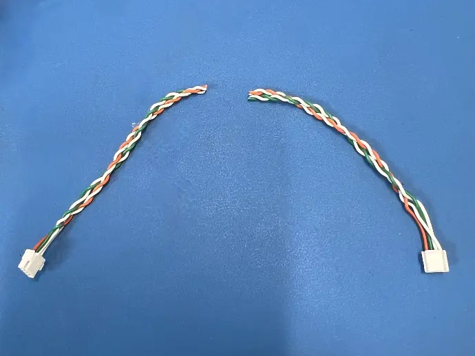
Step Eight
Cut this exactly in half. This allows
two Oculus to ROV termination
leads to be created from each loom.
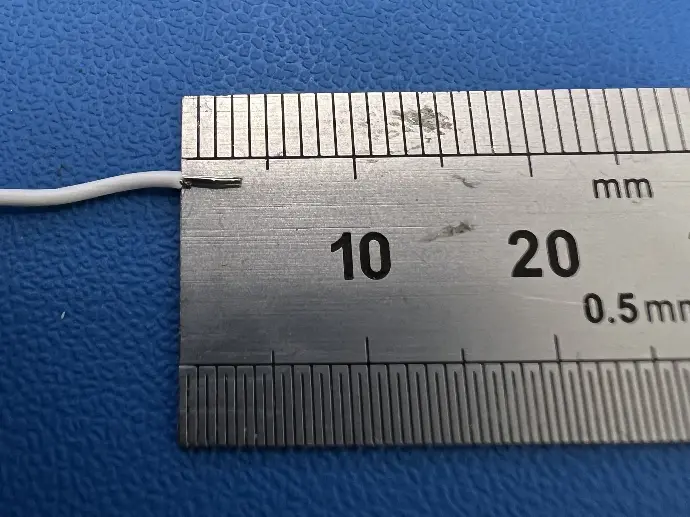
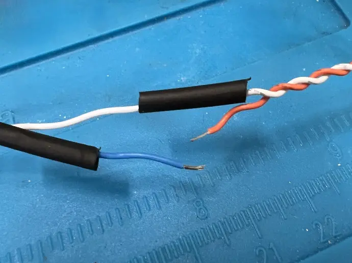
Step Nine
Strip back around 3mm from wires
on the JST loom.
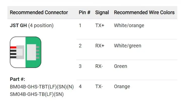
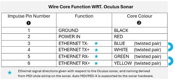
Step Ten
Begin soldering the two cables
together using the following pin out
diagrams:
Step Eleven
Slide each piece of heat shrink over
the solder joins as you go.
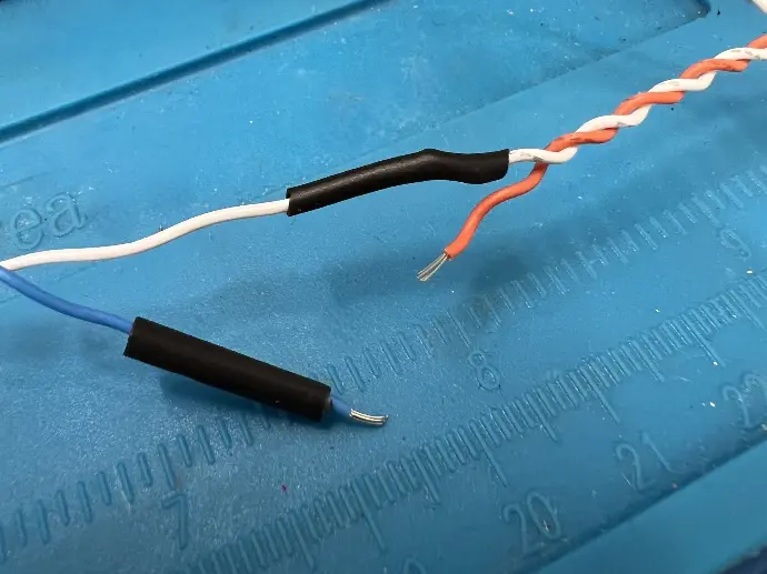
Step Twelve
Use a heat gun to shrink the tubing
into place, protecting the cable
joins.
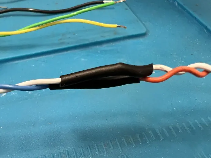
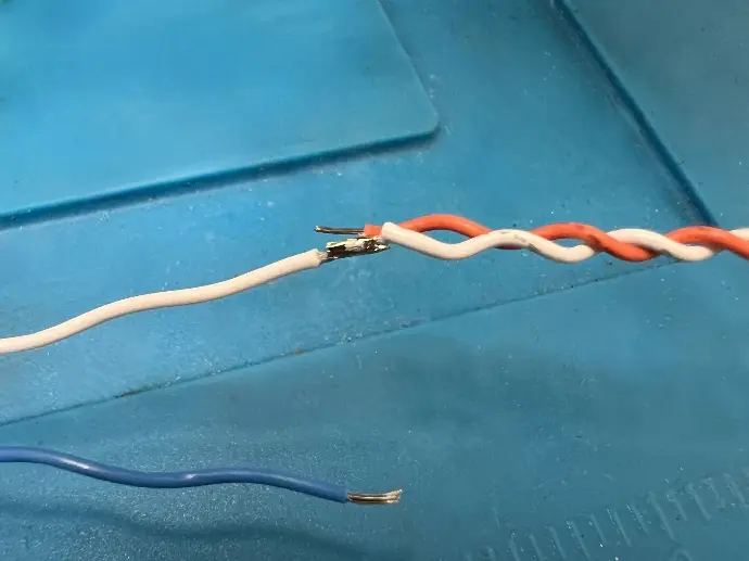
Step Thirteen
Repeat this process for the
Rx and Tx wire pairs.
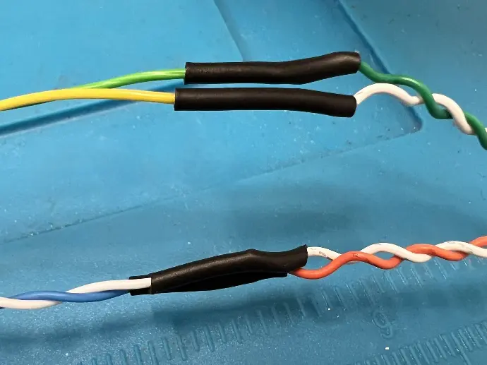
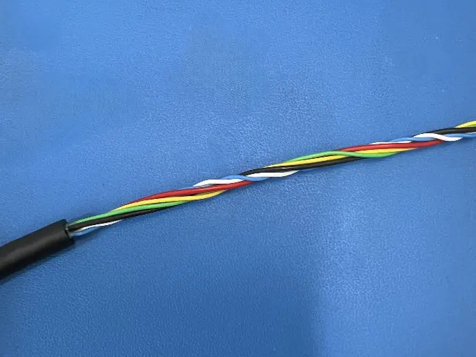
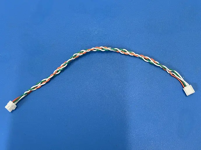
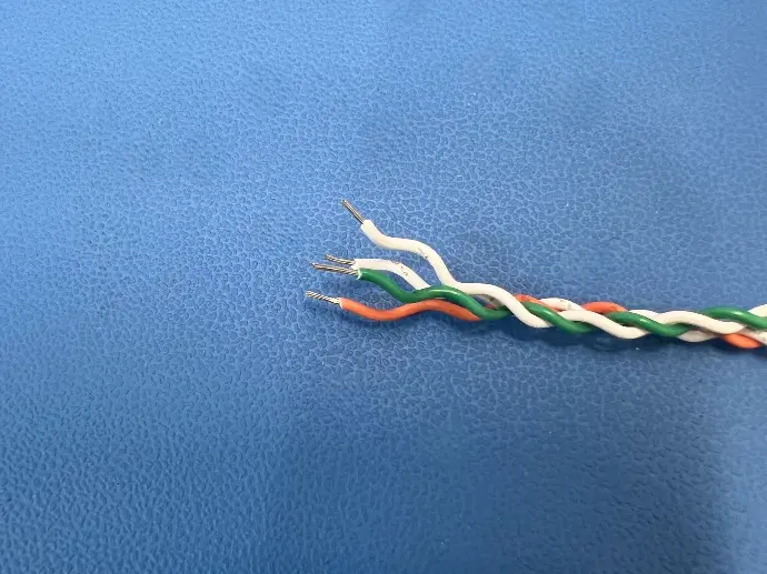
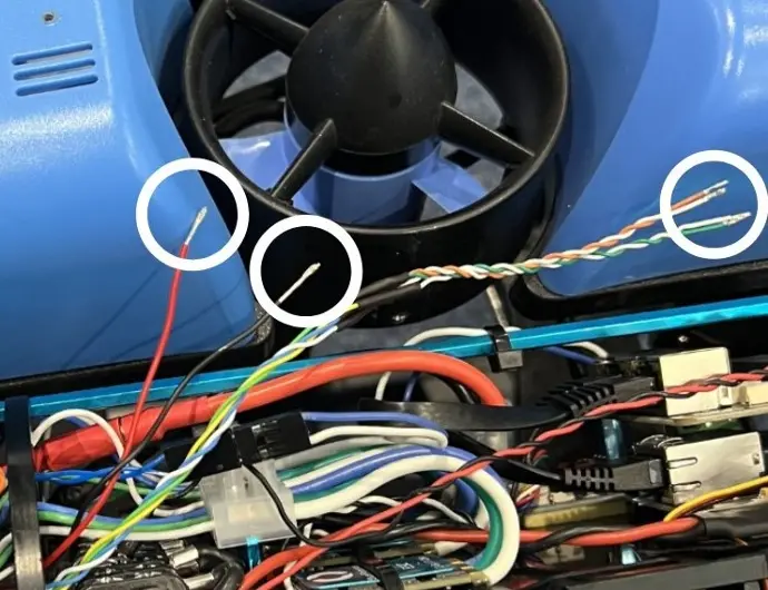
Step Fourteen
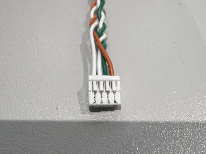
The finished connections should
look something like this.
Make sure the wire pairs are twisted together as much as
possible.
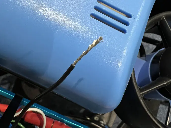
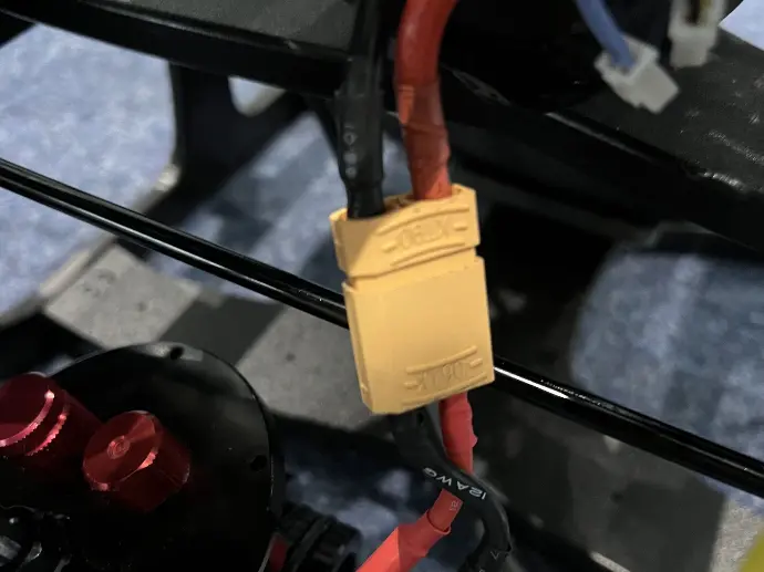
Step Fifteen
Strip back the red and black power
wires by around 10mm.
This needs to be long enough to
terminate beneath a screw later.
Step Sixteen
Using a scalpel, gently remove each of
the JST crimps from the socket.
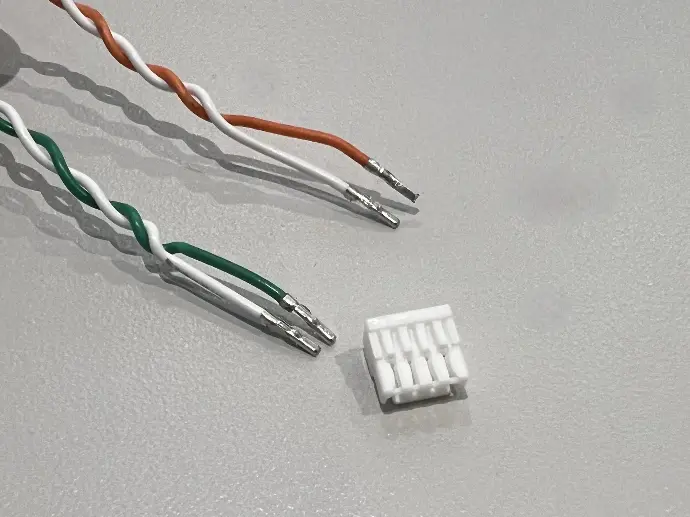
Step Seventeen
Keep the JST
connector as the crimps need to
be re-inserted once the wires are
inside the ROV.
ROV Disassembly
The electronics module needs to be accessible for the installation of the cable. For ROV disassembly, the Blue Robotics website contains the most up to date guides for each variant of the ROV. Be sure to consult the appropriate guide for your ROV.
The ethernet switch required for Oculus operation is an
additional accessory. If your ROV doesn't have this switch already installed, please
consult the Blue Robotics guide below
Ethernet Switch Installation Guide
Cable installation
You will now need to assemble the WetLink Penetrator onto the Oculus cable and install this into the bulkhead of your BlueROV2. Use the link below to access a comprehensive guide on this process from Blue Robotics.
Once your WetLink Penetrator in installed, return here to continue the Oculus installation process.
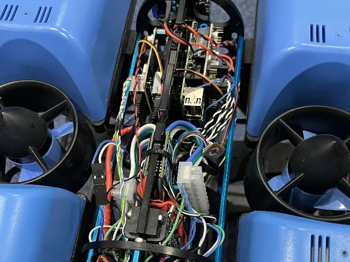
Step One
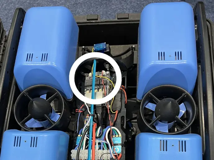
Locate the ethernet PCB on the upper
left of the module. The electronics module has been rotated 90° for easier visibility.
Step Two
Pull the data and power
wires into the central section of the module. (See wires from completed assembly circled above.)
Step Three
Re-insert the JST crimps into the connector.
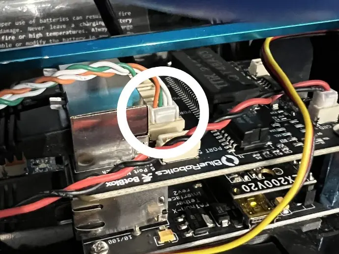
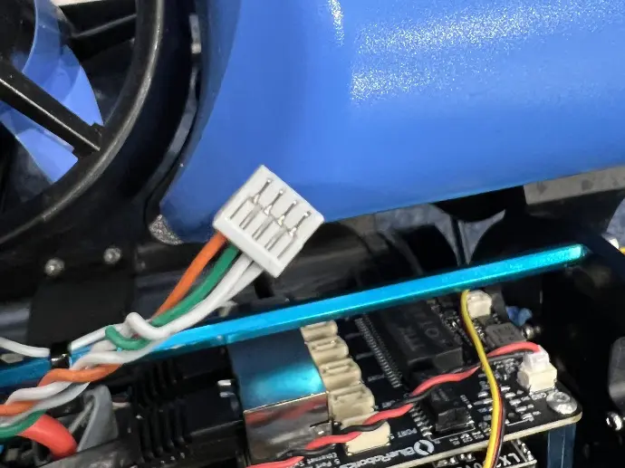
Step Four
Plug the JST connector into one of the three
central sockets on the ethernet PCB. The two outer sockets are reserved for
other specific devices.
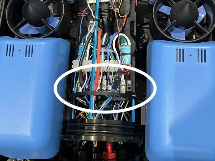
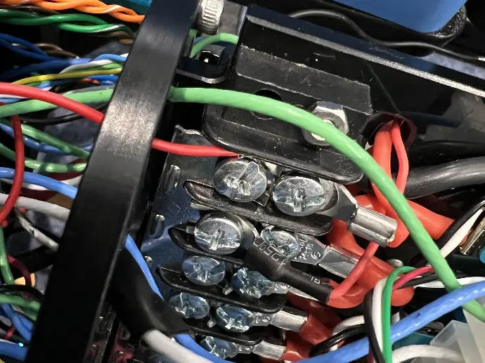
Step Five
Locate the power rail (circled), ground is visible on top and power positive is underneath.
Step Six
Twist up the cores on the black and red wires to
allow for easier termination under the screw contacts.
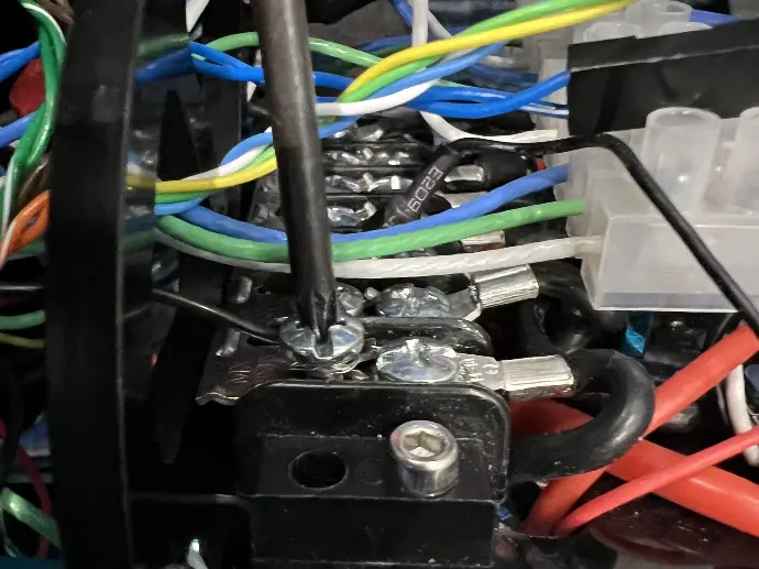
Step Seven
Terminate the black wire underneath an available
screw on the ground rail.
Step Eight
Terminate the red wire underneath an available
screw on the positive rail.
Step Nine
Ensure the data cables
are still twisted into the correct pairs. Check that no cabling is
extruding beyond the electronics module..
Testing
Step One
Ensure that the sonar has
the correct IP address settings. An IP address in the range 192.168.2.XXX, with
subnet mask 255.255.255.0 is required. Plug the IE55 connection
into the Oculus and insert the battery to power-on the ROV. The
first set of beeps indicate that the ROV is powering up. The second set
indicates that the flight modules have activated successfully.
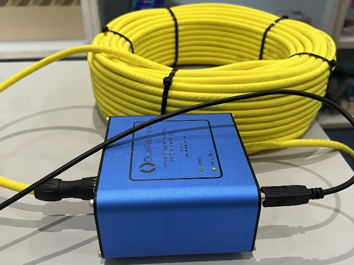
Step Two
Once the ROV has
successfully powered up, plug the tether into the fathom X interface module and plug
the USB cable into the socket on the box.
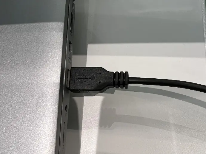
Step Three
Plug the other end of the USB cable into the
topside computer.
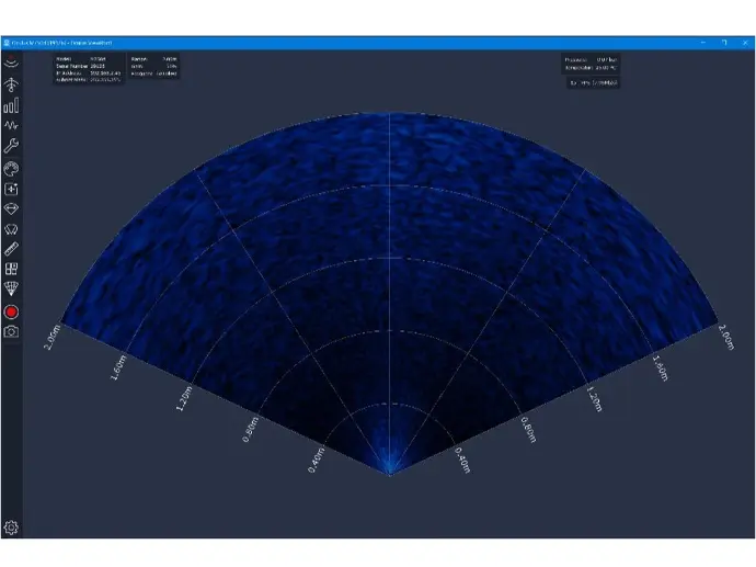
Step Four
Connection should now be possible with the ROV using Q Ground Control. The Oculus sonar should also be visible in ViewPoint. You may need to configure the local adapter settings on the topside PC to connect. (IP in the range 192.168.2.XXX)
If connection is established this means the installation has been successful.
ROV Reassembly
To reassemble your ROV please refer back to the Blue Robotics assembly guide for the most up to up to date information.